Координатно-измерительные машины WENZEL PRODUCT RANGE - страница 136
Навигация
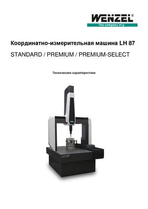 Координатно-измерительные машины LH 87 Wenzel
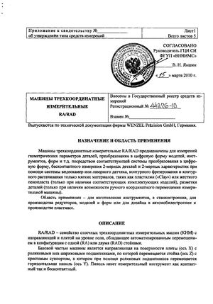 Госреестр. Описание типа 44276-10 Wenzel Машины трехкоординатные измерительные RA, RAD
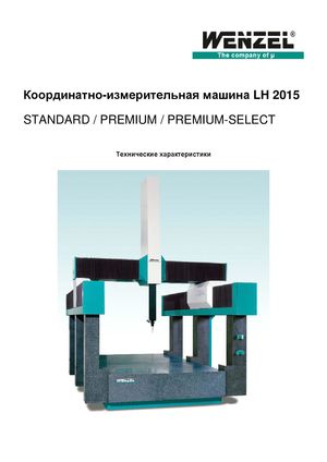 Координатно-измерительные машины Wenzel LH 2015
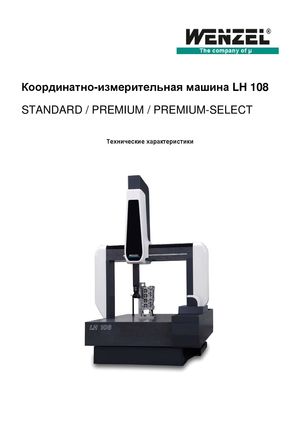 Координатно-измерительные машины Wenzel серии LH 108
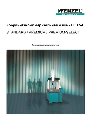 Координатно-измерительное оборудование Wenzel серии LH 54
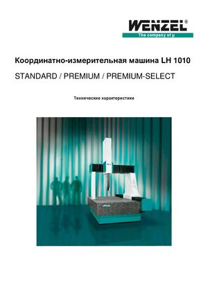 Координатно-измерительные машины Wenzel серии LH 1010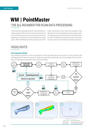
| WM | Pointmaster | WM | PointMaster PRODUCT RANGE SOFTWARE |
| WM | PointMaster | |
| THE ALL-ROUNDER FOR SCAN DATA PROCESSING | |
| The processing of optically and tactile measured data is an | further processing of point clouds and polygonal mesh |
| indispensable and effi cient instrument in the development | right up to the reverse engineering process quality control. |
| and manufacturing process in many industrial sectors and | The innovative processes and process chains are based on |
| applications, such as tool and mould making and in quality | the WM | PointMaster geometry kernel and ensure excel- |
| control. WM | PointMaster primarily supports users in the | lent data quality and outstanding machining processes. |
| HIGHLIGHTS | |
| New Compensation Module | |
| Fully automatic calculation of error-compensated new tool geometry taking into account a nominal geometry, the | Reverse engineering |
| shrinkage factor of materials as well as the original tool geometry (represented in the process diagram for the compen- | A surface boundary on the polymesh is sketched inter- | Artifacts and discontinuities as well as the form guidelines | |
| sation of shrinkage and warpage for tool and mould making). | actively. The Geometry Navigator then calculates the | important for the surface structure are displayed. New func- | |
| optimal boundary curves for this area and approximates | tions such as surface trimming using B-Spline curves, the | ||
| Measurement: |
| CAD | Casting mold | CAD | Selective | Sand | nominal/actual | the surfaces. At the press of a button, the entire sur- | transfer of surfaces created in CAD for reverse engineering | |||
| casting | CAD creation | mold | laser sintering | mold | comparison | face structure is given continuous curvature surfaces | and rule geometry recognition round off the range of functions. | |||
| 11 | ...... | (C2-continuity). A plus point of WM I PointMaster is | ||||||||
| the visual support by the interactive feature “Shading”. | ||||||||||
| CAD |
| Geometry | Manufacturing parameters | – | ||
| 3 | Correction |
manufacturing No Sand mold YOUR ADVANTAGES
| Distortion compensation | parameters | < | ||
| Tolerance | AT A GLANCE |
| 2 | 1 ... | P Shrinkage and distortion correction | |||
| Yes | For tool and die makers | Sophisticated functions and | ||||
| CAD | algorithms | Compensation of the formed or original |
| Measurement: – Casting | |
| Raw | components |
| Casting nominal/actual Casting Yes OK | |
| casting | |
| comparison < Nominal/actual value comparison | |
| Tolerance | Comprehensive format support |
| The user transforms the measured data (scan data = | P |
| actual data) into the coordinate system of the reference | Handling scan and CT data | Support of all common |
| Compensation strategy Analysis of the actual component Alignment actual- to nominal component object (CAD data = target data), starts the analysis and | scan, CAD, CT and CNC formats |
| 3 2 1 receives a deviation color map as result. The measured | Extensive functions |
| deviations are displayed in a so-called deviation color map. | P |
| Measuring points can be taken directly from the analysis | Creation of documents including presentation tools |
| object and transferred to a measuring protocol. Measur- | for measurement reports, documentation | Reports for |
| ing programs created for a tactile measuring machine in | order preparation | Freely available viewer |
| WM I Quartis can be sent via I++ to WM | PointMaster. | Support of numerous data types |
| P | |
| WM | PointMaster then functions as a virtual measuring | |
| Point clouds, polylines, polymasks | Surfaces and curves | |
| represented by sections by nominal/actual comparison machine, calculates the contact point from probe to com- | |
| = Nominal geometry Green section ponent and then sends it back to WM I Quartis. | of higher order | Pixels and voxels | |
| = Nominal geometry (Scan) Red section | CNC traversing polyhedron |
Blue section = Compensated geometry