Балансировочные машины SCHENCK серии HM 20, HM 3, HM 30 - страница 2
Навигация
 Балансировочные машины SCHENCK серии VIRIO 05
 Балансировочные машины SCHENCK серии Pasio 50 SC
 Балансировочные машины SCHENCK серии Distec
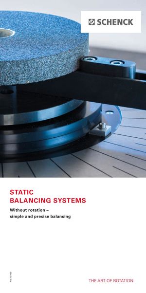 Балансировочные машины SCHENCK серии Static Balancing SyStemS
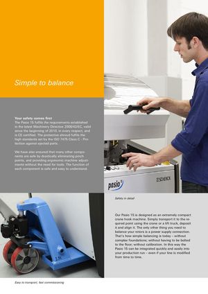 Балансировочные машины SCHENCK серии Pasio 15
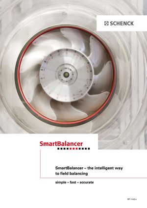 Балансировочные машины SCHENCK серии Smart Balancer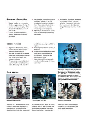
| Sequence of operation | • Acceleration, determination and | • Verification of residual unba lance | ||
| display of unbalance on the | (the measuring unit indicates |
| • Manual loading of the rotor on | measuring instrument, decelera- | whether the required tolerance | |
| the bearing pedestals, closing of | tion. The measured unbalance | has been reached), and unloa- | |
| counter bearings, coup ling of the | values are retained after the | ding of the rotor from the machi- | |
| drive system (belt or universal- | measuring run is completed. | ne. |
joint shaft). Opening of the protection device,
- Closing of protection device. manual unbalance correction (if Start of automatic measuring necessary). sequence:
Special features anti-friction bearings available as option.
- High ease of operation: Hard-
- Indexing angle display in case of
bearing design eliminates the belt drive. need for calibration runs. Automatic measuring cycle with
- Machine provides for unbalance selectable, infinitely variable correction in two planes or sepa- acceleration, measuring and rate correction of static and deceleration times. couple unbalance. Upgradable with many supple-
- Rotors can be mounted on their mentary modules, e.g. for mass original shaft or on a balancing correction. arbor. Balancing with mounted
HM bearing pedestals: Slim, robust bearing Drive system pedestals ensure high overall stiffness, high linearity and extremely low damping. Use of the Schenck hard-bearing principle, with the middle section of the bearing pedestal designed as sturdy dynamometer. Sensors are arranged outside the force path and are therefore insensitive to impacts.
| Underslung belt drive (BU) | Overslung belt drive (BK) | Universal-joint drive (U) |
| Selection of a drive system is deter- | le. Underslung belt drives (BU) pro- | rotor throughput, universal-joint |
| mined by the shape or your rotors. | vide for smooth operation and are | drives (U) in cases where a high |
| Combinations of different drive | universally applicable. Over slung | drive power is required. |
systems on one machine are possib- belt drives (BK) are used for high