Термоусадочное оборудование KEMMLER - страница 12
Навигация
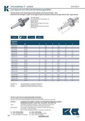
Schrumpff utter 3° - schlank DIN 69871
Shrink chucks 3° for mounting of solid carbide and HSS-tool shanks - slim
Mandrins de frettage 3° pour le serrage de queues d‘outils carbures de type HM et HSS - type élancé
Verwendung: Zur Aufnahme von Werkzeugen mit Zylinderschaft. Application: For mounting straight-shank tools. Application: Pour le serrage d’outils avec queue cylindrique.
| DIN 69871 | AD/B | ≤ 0,003 | G2,5 25.000 min-1 | |||||
| Bestell-Nr. Order no. Référence | SK | d | A | D | D1 | l1 | l2 | |
| 403.72.03 | SK 40 | 3 | 80 | 9 | 15,5 | 6 | – | |
| 403.72.04 | SK 40 | 4 | 80 | 10 | 16,5 | 8 | – | |
| 403.72.05 | SK 40 | 5 | 80 | 11 | 17,5 | 10 | – | |
| 403.72.06 | SK 40 | 6 | 80 | 12 | 18,5 | 36 | 10 | |
| 403.72.08 | SK 40 | 8 | 80 | 14 | 20,5 | 36 | 10 | |
| 403.72.10 | SK 40 | 10 | 80 | 16 | 22,5 | 42 | 10 | |
| 403.72.12 | SK 40 | 12 | 80 | 18 | 24,5 | 47 | 10 | |
| 403.72.03.1 | SK 40 | 3 | 120 | 9 | 19,5 | 6 | – | |
| 403.72.04.1 | SK 40 | 4 | 120 | 10 | 20,5 | 8 | – | |
| 403.72.05.1 | SK 40 | 5 | 120 | 11 | 21,5 | 10 | – | |
| 403.72.06.1 | SK 40 | 6 | 120 | 12 | 22,5 | 36 | 10 | |
| 403.72.08.1 | SK 40 | 8 | 120 | 14 | 24,5 | 36 | 10 | |
| 403.72.10.1 | SK 40 | 10 | 120 | 16 | 26,5 | 42 | 10 | |
| 403.72.12.1 | SK 40 | 12 | 120 | 18 | 28,5 | 47 | 10 | |
| 403.72.06.2 | SK 40 | 6 | 160 | 12 | 26,5 | 36 | 10 | |
| 403.72.08.2 | SK 40 | 8 | 160 | 14 | 28,5 | 36 | 10 | |
| 403.72.10.2 | SK 40 | 10 | 160 | 16 | 30,5 | 42 | 10 | |
| 403.72.12.2 | SK 40 | 12 | 160 | 18 | 32,5 | 47 | 10 |
Ausführung: schlanke Bauform (reduzierte Störkontur) Version: slim design (reduced interference contour) Version: Modèle très étroit (encombrement réduit)
Für Ø 3, 4 und 5 mm nur Hartmetallschäfte verwenden For Ø 3, 4 and 5 mm only solid carbide tool shanks must be used Pour Ø 3, 4 et 5 mm il faut seulement utiliser de queues d‘outils carbures de type HM Hinweis: Aufnahmen für Induktiv-, Kontakt- und Heißluftschrumpfgeräte geeignet. Schafttoleranz bei Ø 3, 4 und 5 mm = h4, bei Ø 6 – Ø 32 mm = h6 Note: Toolholders suitable for induction-, contact- and hot air shrink units. Ø 3, 4, 5 with h4-tolerance and Ø 6 – Ø 32 with h6-tolerance Observation: Porte-outils convenables pour machines à fretter par induction-, par contact-, ou par air chaud.
l1 = max. clamping depth l2 = max. length adjustment range 42 44
l1 = max. profondeur d’insertion l2 = max. course de réglage